

Understanding fuel pump wiring color codes is crucial for maintaining and repairing your vehicle's fuel system. Each colored wire in the fuel pump harness has a specific function, and familiarizing yourself with these codes can help you diagnose and fix issues more effectively. This comprehensive guide will cover everything you need to know about fuel pump wiring color codes, including common colors, their functions, wiring diagrams, troubleshooting tips, and best practices for repair and upgrades.

The fuel pump is a vital component of your vehicle's fuel delivery system, responsible for supplying gasoline from the tank to the engine. A complex wiring system, featuring various colored wires, powers the fuel pump and ensures its proper function. Understanding these color codes is essential for diagnosing and repairing fuel pump issues, as well as for upgrading your vehicle's fuel system.
In this guide, we'll discuss:
Common fuel pump wiring color codes and their functions
How to interpret fuel pump wiring diagrams
Identifying and testing fuel pump wires
Troubleshooting common fuel pump wiring problems
Best practices for repairing and replacing fuel pump wiring
Considerations for upgrading your vehicle's fuel pump wiring
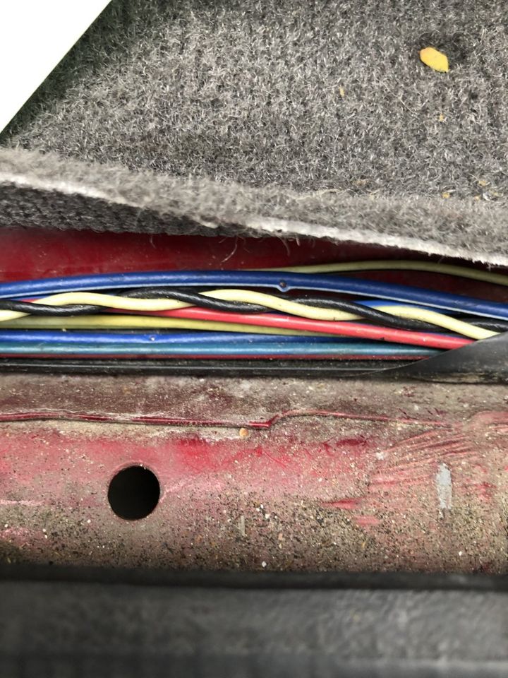
Below is a table of the most common fuel pump wiring colors and their corresponding functions:
| Color Code | Function |
|---|---|
| Blue/black | Positive line from fuel pump |
| Black/red | Constant 12V power |
| Black | Ignition or starter wire |
| Green/red | Indicator light |
| White/black | Ground |
| Purple | Gas gauge wire (GM vehicles) |
| Pink | Fuel gauge sender to gauge |
| Yellow | Bilge blower power (boats) |
| Orange | Accessory feed power |
Please note that color codes may vary slightly depending on the vehicle make and model. Always consult the manufacturer's wiring diagram or a reliable online resource for your specific vehicle.
Fuel pump wiring diagrams provide a visual representation of the wiring layout, making it easier to identify specific wires and their connections. When reading a wiring diagram, pay attention to:
Wire colors and their functions
Connector shapes and sizes
The location of the fuel pump relay, fuse, and other components
The routing of the wires within the vehicle
Common fuel pump wiring configurations include:
Basic fuel pump circuit with relay
Fuel pump wiring with inertia switch (for safety in case of a collision)
Fuel pump wiring with oil pressure switch (more common in older, carbureted engines)
To find the wiring diagram for your vehicle, consult the manufacturer's service manual or search for a reputable online source.
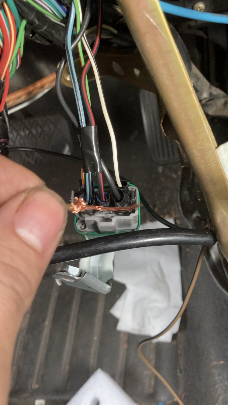
To work on your vehicle's fuel pump wiring, you must first correctly identify the wires in the harness. This can be done through:
Visual inspection: Check for damaged or frayed wires, and corrosion or loose pins on connectors.
Using a multimeter: Test for continuity and voltage to ensure proper connections and power supply.
Tracing wires from the fuel pump connector: Follow each wire from the connector to its destination, referring to the wiring diagram.
When using a multimeter to test fuel pump wires, follow these steps:
Set the multimeter to the appropriate setting (continuity or voltage)
Connect the leads to the appropriate pins or wires
Test for continuity by touching the leads together
Test for voltage by probing the positive and negative wires with the ignition on
Common symptoms of fuel pump wiring issues include:
Fuel pump not running
Fuel pump running continuously
Erratic fuel gauge readings
Engine stalling or misfiring
To troubleshoot these problems, follow this step-by-step guide:
Check for blown fuses and replace if necessary
Test the fuel pump relay for proper operation
Inspect the wiring harness for damage or loose connections
Verify proper voltage at the fuel pump
Always take proper safety precautions when working with fuel pump wiring:
Disconnect the battery to avoid electrical shocks or short circuits
Work in a well-ventilated area and avoid smoking or open flames near the fuel system
Wear protective gloves and eyewear
If you've identified damaged or faulty wiring, it's essential to repair or replace the affected components properly. Here are some tips:
Wire splicing techniques:
Soldering provides a secure and durable connection but requires skill and specialized equipment
Crimping is faster and easier but may be less reliable over time
Always insulate the splice with heat shrink tubing or electrical tape
Replacing damaged connectors and terminals:
Select the correct size and type of replacement parts for your vehicle
Crimp or solder new terminals securely
Apply dielectric grease to prevent corrosion
Routing and securing new wiring harnesses:
Route wires away from heat, moisture, or abrasion sources
Use cable ties or clips to secure the harness in place
Use grommets to protect wires passing through bulkheads or panels
When upgrading your vehicle's fuel pump wiring for improved performance or reliability, consider:
Benefits of using larger gauge wire:
Reduces voltage drop
Improves fuel pump efficiency
Especially important for high-flow fuel pumps or high-performance fuel systems
Adding a secondary ground wire:
Ensures a reliable electrical connection
Prevents voltage fluctuations
Use the same gauge as the positive wire and connect to a clean, bare metal surface
Installing a higher capacity relay and fuse:
Accommodates increased electrical load from upgraded fuel pumps
Consult the fuel pump manufacturer's recommendations for appropriate ratings
Considerations for high-performance fuel systems:
Use larger gauge wires to handle increased demands
Install a more robust relay
Add additional grounding points
Ensure proper shielding from heat and vibration
Mastering fuel pump wiring color codes is essential for diagnosing, repairing, and upgrading your vehicle's fuel system. By understanding common color codes, interpreting wiring diagrams, and following best practices for troubleshooting and repair, you can ensure your fuel pump operates reliably and efficiently.
Always prioritize safety when working with fuel pump wiring and consult a professional if you're unsure about any aspect of the process. With the knowledge and tools provided in this guide, you'll be well-prepared to tackle fuel pump wiring issues and keep your vehicle running smoothly.
The fuel pump relay is responsible for supplying power to the fuel pump when the ignition is turned on. It acts as a switch, controlling the flow of electricity to the pump.
To test the fuel pump relay, remove it from the vehicle and use a multimeter to check for continuity between the relay terminals. You can also apply 12V power to the relay and listen for a clicking sound, indicating proper operation.
If you notice corrosion on the fuel pump wiring connectors, clean the affected areas with a wire brush or sandpaper, and apply dielectric grease to prevent future corrosion. Replace severely damaged connectors.
No, it is essential to use automotive-grade wire with the appropriate gauge and insulation properties when replacing or upgrading fuel pump wiring. Using the wrong type of wire can lead to electrical issues or even fire hazards.
The inertia switch is a safety device that cuts off power to the fuel pump in the event of a collision. This helps prevent fuel leaks and potential fires by stopping the flow of gasoline.
The location of the fuel pump wiring harness varies depending on the make and model of your vehicle. Consult your vehicle's service manual or search for a specific guide online to find the exact location.
Erratic fuel gauge readings can be caused by a faulty fuel pump sending unit or damaged wiring. Check the wiring harness for any signs of damage, and test the sending unit using a multimeter. Replace any faulty components as necessary.
While it is possible to upgrade your vehicle's fuel pump without upgrading the wiring, it is not recommended. The existing wiring may not be able to handle the increased electrical load, leading to potential issues or even damage to the fuel pump.
Signs of a failing fuel pump relay include the engine not starting, stalling, or misfiring. You may also notice the fuel pump running continuously or not running at all. If you suspect a faulty relay, test it using a multimeter or replace it with a known working unit.
It is a good practice to inspect your vehicle's fuel pump wiring at least once a year or during regular maintenance intervals. Look for any signs of damage, corrosion, or loose connections, and address any issues promptly to prevent potential problems.

Miguel started tinkering with car radios as a teenager, fascinated by the intricate dance of wires and circuits. This passion led him to pursue a career as an automotive electrician. For the past 10 years, Miguel has tackled everything from flickering headlights to mysterious electrical gremlins. He thrives on troubleshooting electrical problems and enjoys sharing his knowledge to empower car owners to understand their vehicles better.


