
Relays are essential components in automotive electrical systems, allowing low-current circuits to control high-current loads safely. This guide provides a detailed overview of wiring a 5-pin automotive relay, ensuring proper installation and operation.

A relay acts as an electromechanical switch, using a low-current control signal to operate a high-current load circuit. By energizing an electromagnet, the relay actuates a set of contacts, opening or closing the load circuit. Relays offer electrical isolation between the control and load circuits, protecting sensitive electronic components from potential damage caused by high currents or voltage spikes.
Incorporating relays into automotive electrical systems offers several advantages. They enable low-current switches or control modules to safely operate high-current loads, such as lights, fans, or winches. Additionally, relays extend the lifespan of switches and control components by isolating them from the high-current load, minimize voltage drops, and reduce the risk of electrical interference in sensitive circuits.
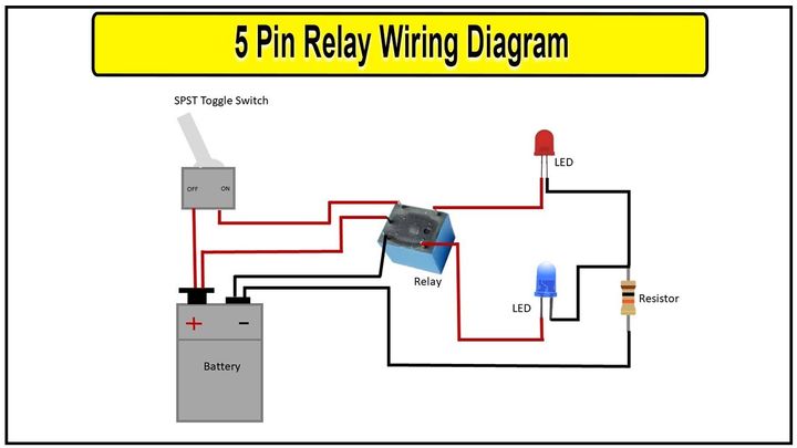
The 5-pin relay is a common SPDT (Single Pole, Double Throw) configuration widely used in automotive applications. It has five terminals, each serving a specific function:
| Pin | Function |
|---|---|
| 30 (Common) | Connects to the positive power source (battery) through a fuse, providing power to the relay and load circuit. |
| 87 (Normally Open) | Connects to the positive terminal of the load you want to control (e.g., lights, fans, winches). |
| 85 (Coil Ground) | Connects to the vehicle's chassis ground, completing the coil circuit. |
| 86 (Coil Power) | Connects to the positive side of the control circuit (switch or control module). |
| 87a (Normally Closed) | Optional pin to connect a component you want powered when the relay is off. |
The terms "normally open" and "normally closed" refer to the default state of the relay's contacts when the coil is not energized. Pin 87 is normally open, meaning the circuit is open (disconnected) when the relay is not activated. Conversely, pin 87a is normally closed, allowing current to flow through it when the relay is off.
Proper fusing is crucial to protect the relay and electrical system from potential damage caused by overcurrent situations. The power wire connected to pin 30 (Common) must be fused according to the maximum current rating of the load being controlled.
The wire gauge used for the power and load connections should be appropriate for the current requirements of the circuit. Undersized wires can lead to excessive voltage drops, overheating, and potential fire hazards.
The positive terminal of the load you want to control should be connected to pin 87 (Normally Open). When the relay is energized, this pin will connect to the power source (pin 30), allowing current to flow to the load.
If your application requires a backup or secondary load to be powered when the relay is off, you can connect it to pin 87a (Normally Closed). This pin is typically left disconnected if not needed.
Proper grounding is essential for the relay to function correctly and prevent electrical interference or damage. Pin 85 (Coil Ground) should be connected directly to the vehicle's chassis ground or a known good ground point, ensuring a clean, tight connection to minimize resistance and potential voltage drops.
The control circuit, which energizes the relay coil, is connected to pin 86 (Coil Power). This pin should be connected to the positive side of the switch, control module, or other triggering source that will activate the relay.
It is crucial to maintain the correct polarity when wiring the control circuit. The negative side of the switch or control source must be connected to the vehicle's chassis ground or a known good ground point. Reversing the polarity can damage the control components or prevent the relay from functioning correctly.
When selecting a relay, consider the following specifications and ratings:
| Specification | Description |
|---|---|
| Coil Voltage Rating | The voltage required to energize the relay's electromagnet (typically 12V for automotive applications). |
| Coil Current Rating | The maximum current the coil can draw without overheating or damaging the relay. |
| Contact Current Rating | The maximum current the relay can safely switch, which should exceed the load's maximum current draw. |
| Operating Temperature Range | Typically between -40°C (-40°F) and 125°C (257°F) for automotive relays. |
| Coil Resistance | A measure of the electrical resistance within the relay's electromagnet coil, essential for calculating current draw. |
| Physical Dimensions | Relays come in various sizes and mounting styles, so consider the available space in your application. |
The mounting style and location of the relay are crucial considerations for proper operation and accessibility. Common mounting styles include:
Panel mount: Installed in the vehicle's fuse box or relay center.
Surface mount: Secured to a flat surface using screws or adhesive.
Ensure the mounting location is easily accessible for maintenance and troubleshooting.
5-pin relays commonly use quick-connect terminals or spade terminals for wiring connections. Ensure all connections are tight and free from corrosion or damage.
Proper insulation and protection of the relay and wiring are essential for reliable operation and safety. Use appropriate wire loom or conduit to protect the wiring from potential damage or abrasion. Additionally, consider using relay sockets or enclosures to protect the relay from moisture, dust, and other environmental factors.
Here are some common wiring configurations for 5-pin automotive relays:
| Component | Connection |
|---|---|
| Pin 30 (Common) | Fused battery positive (+12V) |
| Pin 87 (Normally Open) | Positive terminal of accessory lights |
| Pin 85 (Coil Ground) | Vehicle chassis ground |
| Pin 86 (Coil Power) | Positive side of light switch |
| Negative side of light switch | Vehicle chassis ground |
| Negative terminal of accessory lights | Vehicle chassis ground |
| Component | Connection |
|---|---|
| Pin 30 (Common) | Fused battery positive (+12V) |
| Pin 87 (Normally Open) | Positive terminal of electric fan |
| Pin 85 (Coil Ground) | Vehicle chassis ground |
| Pin 86 (Coil Power) | Positive side of temperature switch or control module |
| Negative side of temperature switch or control module | Vehicle chassis ground |
| Negative terminal of electric fan | Vehicle chassis ground |
Connect pin 30 (Common) to the positive terminal of the main battery or power source, fused appropriately.
Connect pin 87 (Normally Open) to the positive terminal of the winch or auxiliary battery.
Connect pin 85 (Coil Ground) to the vehicle's chassis ground.
Connect pin 86 (Coil Power) to the positive side of the winch control switch or battery isolator.
Connect the negative side of the winch control switch or battery isolator to the vehicle's chassis ground.
Connect the negative terminal of the winch or auxiliary battery to the vehicle's chassis ground.
Before testing the relay operation, carefully inspect all wiring connections for proper termination, polarity, and tightness. Loose or corroded connections can lead to intermittent or unreliable operation.
To test the relay operation:
Disconnect the load from pin 87 (Normally Open) to prevent accidental activation during testing.
Apply power to the control circuit by activating the switch or control source connected to pin 86 (Coil Power).
Use a multimeter or test light to verify that pin 87 (Normally Open) is receiving power when the relay is energized.
If pin 87 is not receiving power, check the control circuit wiring, fuses, and relay coil for proper operation.
Common wiring issues include reversed polarity in the control circuit or load connections, inadequate wire gauge for the load current, poor grounding or loose ground connections, damaged or corroded wiring or terminals, and incorrect relay specifications for the application.
If you encounter persistent issues or are unsure about the wiring or relay selection, it is recommended to seek professional assistance from an automotive electrician or a qualified technician.
Wiring a 5-pin automotive relay correctly is essential for ensuring the safe and reliable operation of your vehicle's electrical accessories. By following the guidelines outlined in this guide, you can confidently tackle relay wiring projects and enjoy the benefits of enhanced electrical system performance.
Remember to prioritize safety by adhering to proper fusing, grounding, and wire gauge selection practices. If you encounter any difficulties or have concerns about your specific application, don't hesitate to consult with a professional automotive electrician or refer to the manufacturer's documentation for guidance.
A relay allows a low-current circuit to control a high-current circuit. It acts as an electrically operated switch to turn components on and off.
When the coil (pins 85 and 86) is energized, it creates a magnetic field that switches the common pin 30 connection from normally closed 87a to normally open 87.
Relays protect sensitive electronics from high currents, extend switch lifespan, minimize voltage drops, and reduce electrical interference.
"Normally open" means the contacts are open when the relay is off, while "normally closed" means the contacts are closed when the relay is off.
Pin 85 (Coil Ground) should be connected directly to the vehicle's chassis ground or a known good ground point.
Consider the coil voltage/current rating, contact current rating, operating temperature range, coil resistance, and physical dimensions.
Mount the relay in an accessible location using panel mount, surface mount, or within a fuse box/relay center. Protect it from moisture and dust.
Use an appropriate wire gauge for the maximum current of the load circuit to prevent overheating and voltage drops.
Disconnect the load, apply power to the control circuit, and verify pin 87 is receiving power when the relay is energized.
Common issues include reversed polarity, inadequate wire gauge, poor grounding, damaged wiring/terminals, and incorrect relay specifications.
Miguel started tinkering with car radios as a teenager, fascinated by the intricate dance of wires and circuits. This passion led him to pursue a career as an automotive electrician. For the past 10 years, Miguel has tackled everything from flickering headlights to mysterious electrical gremlins. He thrives on troubleshooting electrical problems and enjoys sharing his knowledge to empower car owners to understand their vehicles better.