
Electric motors and generators are crucial components in the automotive industry, powering everything from electric vehicles to engine starters and alternators. At the heart of these machines are two essential parts: the rotor and the stator. The rotor is the rotating element, while the stator is the stationary part surrounding it. The interaction between these two components enables the conversion of electrical energy into mechanical energy, or vice versa.
In this article, we will explore the fundamentals of rotors and stators, their construction, types, and how they work together in motors and generators. We will also discuss their applications in the automotive industry and the advantages and challenges associated with rotor-stator machines.

The rotor and stator are the two main components of an electric machine. Their interaction is based on the principle of electromagnetic induction, discovered by Michael Faraday in 1831. Faraday's law states that when a conductor moves through a magnetic field, an electromotive force (EMF) is induced in the conductor. Conversely, when an electric current flows through a conductor, it creates a magnetic field around it.
| Component | Definition | Function |
|---|---|---|
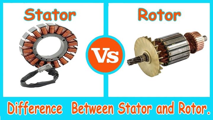
| Rotor | The rotating part of an electric machine, consisting of a shaft and a core with conductors arranged around its periphery. | In motors, the rotor receives electrical energy from the stator's magnetic field and converts it into mechanical energy, causing the shaft to rotate. In generators, the rotor is driven by an external mechanical force and its rotation induces electrical energy in the stator windings. |
| Stator | The stationary part of an electric machine, consisting of a core made of laminated steel and windings arranged in slots around the inner periphery. | The stator creates a rotating magnetic field that interacts with the rotor's conductors to produce torque in motors or induce electrical energy in generators. |
Rotors come in various designs, each with its own advantages and applications. The two most common types are the squirrel cage rotor and the wound rotor.
The squirrel cage rotor is the most widely used type in induction motors. It features a cylindrical core made of steel laminations with parallel slots running along its periphery. Aluminum or copper bars are inserted into these slots and connected at both ends by end rings, forming a "squirrel cage" structure. This simple and rugged design offers several benefits:
Low cost and easy manufacturing
High reliability and low maintenance
Good starting torque and running performance
Squirrel cage motors are commonly found in automotive applications such as engine cooling fans, windshield wipers, power window motors, seat adjustment motors, and fuel pumps.
A wound rotor has a cylindrical core with insulated copper windings placed in slots along its periphery. These windings are connected to slip rings mounted on the shaft, allowing external resistors to be connected to modify the motor's starting and speed control characteristics. While more complex and expensive than squirrel cage rotors, wound rotors offer advantages such as:
Excellent starting torque
Smooth acceleration and deceleration
Adjustable speed control
Reduced starting current
Wound rotor motors are used in applications requiring high starting torque and adjustable speed control, such as electric vehicle traction motors, hoists, cranes, and elevators.
In addition to squirrel cage and wound rotors, there are other designs used in specific applications:
Permanent magnet (PM) rotors: PM rotors use permanent magnets instead of windings to create a magnetic field. They offer high efficiency, compact size, and excellent power density, making them suitable for applications like electric vehicle traction motors and high-performance servo motors.
Reluctance rotors: Reluctance rotors have a salient pole structure that exploits the difference in magnetic reluctance between the rotor's axis and the air gap. They feature simple construction, high efficiency, and good speed control capabilities, making them suitable for applications such as electric vehicle traction motors and high-speed spindle drives.
The stator is the stationary part of an electric machine, consisting of a core made of thin steel laminations stacked together to form a hollow cylinder. The laminations are insulated from each other to reduce eddy current losses and improve efficiency. The stator core provides a low-reluctance path for the magnetic flux and supports the stator windings.
Stator windings are classified into two main types: distributed windings and concentrated windings.
| Winding Type | Description | Advantages | Applications |
|---|---|---|---|
| Distributed | Coils are distributed in slots around the stator core's periphery, with each coil spanning several slots. Produces a sinusoidal magnetic field distribution. | Smooth torque production, low harmonic content | General-purpose applications, such as industrial motors, generators, and automotive alternators |
| Concentrated | Coils are concentrated around each pole, with each coil spanning a single tooth or a small number of teeth. | Shorter end turns (reduced copper losses and improved efficiency), higher slot fill factor (more compact designs), reduced manufacturing complexity and cost | High-performance applications, such as electric vehicle traction motors and aerospace generators |
To ensure reliable performance and long service life, stator windings must be adequately insulated and cooled. Insulation systems typically consist of enamel-coated copper conductors, slot liners, phase separators, and impregnating varnishes or resins. The insulation system's thermal class determines the maximum operating temperature of the machine.
Cooling systems for stators can be classified into two main categories:
Air cooling: Forced air circulation using fans or blowers, suitable for small to medium-sized machines.
Liquid cooling: Circulation of a cooling fluid, such as water or oil, through channels in the stator core or housing, suitable for large and high-power machines.
Proper insulation and cooling are essential for maintaining the stator's temperature within safe limits, preventing premature failure, and ensuring reliable operation.
In an AC motor, the stator windings are supplied with a three-phase alternating current, creating a rotating magnetic field. The speed of this field, known as the synchronous speed, depends on the supply frequency and the number of poles in the stator.
As the stator's rotating magnetic field sweeps across the rotor's conductors, it induces an EMF in them, causing currents to flow. These currents create a magnetic field that interacts with the stator's field, producing a torque that causes the rotor to rotate. The torque is proportional to the strength of the magnetic fields and the sine of the angle between them.
In an induction motor, the rotor always rotates at a speed lower than the synchronous speed, with the difference known as slip. Slip is necessary for inducing currents in the rotor and producing torque. As the load on the motor increases, the slip increases, allowing the motor to develop more torque.
The speed of an induction motor can be controlled by various methods, such as:
Voltage control: Adjusting the supply voltage to change the stator's magnetic field strength and the rotor's induced currents.
Frequency control: Adjusting the supply frequency to change the synchronous speed and the rotor's speed.
Pole-changing: Altering the number of poles in the stator winding to change the synchronous speed.
Slip control: Modifying the rotor's resistance or reactance to change the slip and the motor's torque-speed characteristics.
These speed control methods are widely used in automotive applications, such as electric vehicle traction motors and engine cooling fans, to optimize performance and efficiency.
In a generator, the rotor is driven by a prime mover, such as an internal combustion engine, a steam turbine, or a wind turbine. As the rotor rotates, its magnetic field sweeps across the stator windings, inducing an EMF in them. This EMF produces an alternating current (AC) output, which can be used to power electrical devices or fed into the power grid.
The induced EMF in the stator windings depends on the strength of the rotor's magnetic field, the speed of rotation, and the number of turns in the windings. The generated AC power has a frequency equal to the product of the rotor's speed and the number of pole pairs in the machine.
In synchronous generators, the rotor's magnetic field is produced by either permanent magnets or a DC excitation winding. The rotor rotates at the same speed as the stator's magnetic field, ensuring a constant frequency output. In induction generators, the rotor's magnetic field is induced by the stator's magnetic field, similar to an induction motor. The rotor rotates at a speed slightly higher than the synchronous speed, allowing it to generate electrical power.
Proper excitation control is essential for maintaining the generator's output voltage and reactive power balance, ensuring stable operation and grid compatibility. Excitation systems can be either brushless or static:
Brushless excitation systems use a small AC generator (exciter) mounted on the same shaft as the main generator. The exciter's output is rectified and fed to the rotor's field winding, creating a DC magnetic field.
Static excitation systems use power electronic converters to supply DC current to the rotor's field winding, eliminating the need for brushes and slip rings.
Rotor-stator machines find numerous applications in the automotive industry, ranging from electric vehicle propulsion to auxiliary systems. Some of the key applications include:
| Machine Type | Applications |
|---|---|
| Induction motors | Engine cooling fans, windshield wipers, power window motors, seat adjustment motors, fuel pumps |
| Synchronous motors and generators | Electric vehicle traction motors, integrated starter-generators (ISGs), alternators for conventional vehicles |
| Doubly-fed induction generators | Wind power applications, hybrid vehicles with wind turbine range extenders |
| Permanent magnet motors and generators | Electric vehicle traction motors, high-performance starter motors, alternators for mild hybrid vehicles |
The choice of rotor-stator machine for a specific application depends on factors such as power requirements, speed range, efficiency targets, and cost constraints.
Rotor-stator machines offer several advantages in terms of efficiency and reliability:
High efficiency: Modern electric machines can achieve efficiencies above 90%, reducing energy consumption and operating costs.
Robustness: Squirrel cage induction motors, in particular, are known for their ruggedness and ability to withstand harsh environments.
Low maintenance: With proper design and manufacturing, rotor-stator machines require minimal maintenance, reducing downtime and service costs.
Despite their reliability, rotor-stator machines may experience issues that require maintenance or troubleshooting, such as bearing failures, winding insulation breakdown, or rotor bar failures. Regular inspections, condition monitoring, and preventive maintenance can help identify and address these issues before they lead to machine failure.
Ongoing research and development efforts aim to improve the performance, efficiency, and sustainability of rotor-stator machines. Some notable trends include:
Advanced materials: New materials, such as high-temperature superconductors and nanocomposite insulators, can enhance the machines' power density and efficiency.
3D printing: Additive manufacturing techniques enable the creation of complex geometries and optimized designs, reducing weight and improving performance.
Integrated power electronics: Embedding power electronic converters into the machine's structure can reduce size, weight, and cost while improving controllability.
Sustainable manufacturing: Eco-friendly materials and processes, such as recycled copper and biodegradable insulation, can reduce the environmental impact of rotor-stator machines.
As the automotive industry continues to evolve towards electrification and sustainability, rotor-stator machines will play an increasingly important role in powering the vehicles of the future.
Rotors and stators are the essential components that enable electric motors and generators to convert energy and drive modern machinery. By understanding the fundamentals of these components, their construction, types, and interactions, we can better appreciate their crucial role in the automotive industry and beyond. As technology advances, rotor-stator machines will continue to evolve, offering higher efficiency, improved performance, and greater sustainability. The dynamic duo of the rotor and stator will undoubtedly remain at the heart of electric machines, powering the future of transportation and industry.
The rotor is the rotating part of an electric motor or generator. It interacts with the magnetic field produced by the stator to convert electrical energy into mechanical rotation or vice versa.
Rotors are commonly made of laminated steel cores with aluminum or copper bars/windings.
A squirrel cage rotor has aluminum or copper bars inserted into the steel core slots and shorted at the ends by end rings, forming a "squirrel cage" shape.
A wound rotor has insulated copper windings placed in the steel core slots and connected to slip rings, allowing external resistors for speed control.
A salient pole rotor has distinct projected poles wound with copper wire to form individual electromagnets supplied by DC current.
The stator's main function is to produce a rotating magnetic field that interacts with the rotor's magnetic field to generate torque in a motor or induce current in a generator.
Stator windings can be arranged in distributed or concentrated patterns around the stator core slots.
Stator windings require high insulation to withstand the high voltages induced in them during operation.
Stators can be cooled by air using fans/blowers or by circulating a liquid coolant through channels in the core/housing.
The strength of magnetic fields, number of poles, air gap between rotor and stator, and rotational speeds affect the interaction and performance.
Miguel started tinkering with car radios as a teenager, fascinated by the intricate dance of wires and circuits. This passion led him to pursue a career as an automotive electrician. For the past 10 years, Miguel has tackled everything from flickering headlights to mysterious electrical gremlins. He thrives on troubleshooting electrical problems and enjoys sharing his knowledge to empower car owners to understand their vehicles better.